For dilution refrigerators and vacuum cryogenic systems
Cryogenic coaxial MI cable assemblies
Kamet supplies mineral insulated (MI) coaxial cable assemblies for cryogenic and vacuum environments, including dilution refrigerators, quantum computing systems, and cryogenic test setups.
These cryogenic coaxial cables combine high mechanical robustness, excellent vacuum compatibility (low outgassing), and stable performance under extreme thermal cycling.
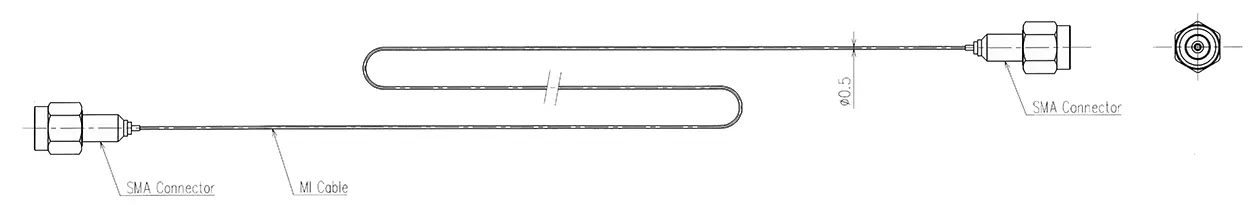
Available as fully assembled coaxial cables (e.g. with SMA connectors) or as MI cable for custom integration.
Product summary
- Designed for cryogenic and vacuum applications
- Engineering-driven customization and support
- Prototype-to-series development approach
- Compatible with demanding scientific and semiconductor environments
- Supplied as cable or complete assembly
About cryogenic coaxial MI cables
Cryogenic coaxial MI cables consist of a central conductor, surrounded by mineral insulation (SiO₂ or MgO) and a seamless metallic sheath, typically stainless steel.
Compared to conventional polymer-insulated semi-rigid coaxial cables, MI coaxial cables offer significant advantages in demanding cryogenic and vacuum environments:
- High mechanical robustness
- Excellent vacuum compatibility (no outgassing)
- Resistance to thermal shock
- Stable performance under repeated temperature cycling
These properties make them particularly suitable for use inside dilution refrigerators, where reliable signal transmission under extreme conditions is required.
Common applications
Typical applications of cryogenic coaxial MI cable assemblies include:
- Dilution refrigerators (internal signal routing and sensor readout)
- Quantum computing systems
- Cryogenic experimental setups
- Vacuum instrumentation requiring robust signal transmission
- Resistive attenuation lines in low-temperature environments
Impedance vs resistance – important clarification
Although both are expressed in ohms (Ω), characteristic impedance and DC resistance are fundamentally different parameters:
Characteristic impedance (Z₀)
- Governs high-frequency signal transmission
- Determined by cable geometry and dielectric properties
- Independent of cable length
DC conductor resistance (Ω/m)
- Represents resistive losses
- Scales with cable length
For cryogenic coaxial applications, it is essential to clearly define whether the requirement relates to impedance matching (e.g. 50 Ω systems) or resistive/attenuation behavior.

Our standard cryogenic coaxial cable configurations
Kamet offers various configurations of cryogenic coaxial MI cable assemblies. Below is an overview of common design options. Other configurations (diameter, materials, impedance) are available on request.
| Conductor material | Insulation | Sheath material | Typical OD | Impedance options | Typical length |
|---|---|---|---|---|---|
| Nichrome 80/20 | SiO₂ | Stainless steel | 0.5 mm | 50 Ω / 30 Ω / ~20 Ω | 3.0 m |
| 316L stainless steel | SiO₂ | Stainless steel | 0.5 mm | ~20–30 Ω | 3.0 m |
| Nichrome 80/20 | MgO (on request) | Stainless steel | 0.5 mm | design dependent | custom |
How can we help you today?
Request a quotation for the cable you need for your sensor.
Specifications and physical properties
Physical and electrical properties
- Sheath: stainless steel (other alloys on request)
Insulation:- SiO₂ (preferred for stable geometry and lower thermal conductivity)
- MgO (available on request)
- Outer diameter: typically 0.5 mm
- Length: standard 3 m, other lengths available
Characteristic impedance:
- 50 Ω (thin conductor design)
- Alternative designs (30 Ω / ~20 Ω)
- Conductor resistance: defined in Ω/m
- Insulation resistance: ≥ 5 MΩ at 100 VDC
- Frequency performance: to be validated in customer system
Connector and termination options
Cryogenic coaxial assemblies can be supplied with various termination options.
- Miniature SMA connectors (typical for internal cryogenic wiring)
- Custom termination solutions
- MI cable without connectors for customer integration
Key considerations for cryogenic environments:
- Solder joints may experience stress under thermal cycling
- Elastomer seals may lose elasticity at low temperatures
- Laser welding or alternative joining techniques can be evaluated
- Connector selection depends on system design and vacuum boundary
Bending and installation guidelines
Mineral insulated coaxial cables offer flexibility, but bending influences high-frequency performance.
- Minimum bending radius (mechanical): ≥ 3 × OD
- Recommended for signal stability: 10–20 × OD
Final routing should always be validated within the actual system.
Mounting and integration
Cryogenic coaxial MI cables can be integrated in various ways:
- Routed inside vacuum chambers
- Fixed using clamps or brackets
- Integrated into sub-assemblies
- Connected to hermetic feedthrough systems
The optimal integration strategy depends on impedance stability, thermal gradients, and mechanical constraints.
Evaluation and qualification approach
Kamet supports prototype-driven validation to ensure optimal performance in your application.
Typical evaluation steps include:
- Dimensional verification
- DC resistance measurement
- Insulation resistance testing
- Termination inspection
- System-level RF validation (performed by customer)
Multiple design variants can be supplied to allow direct comparison between conductor materials and impedance configurations.

Do you have a question about this MI cable assembly?
Cryogenic and vacuum environments can be complex. Contact our in-house experts today, and together you can find the best MI solution for your needs.